this post has undergone a couple of edits, which are amendments at the bottom
some pieces out of my current notebook. if you want to “iterate”, run the last three cells repeatedly in sequence.
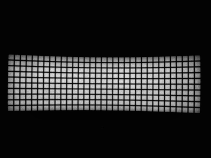
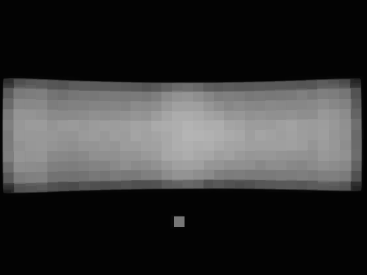
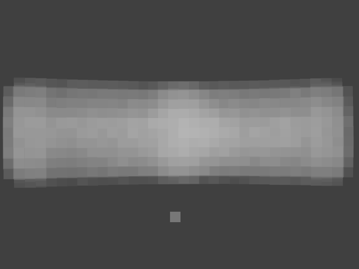
actual, actual compensated for brightness variation (actual divided by estimate):
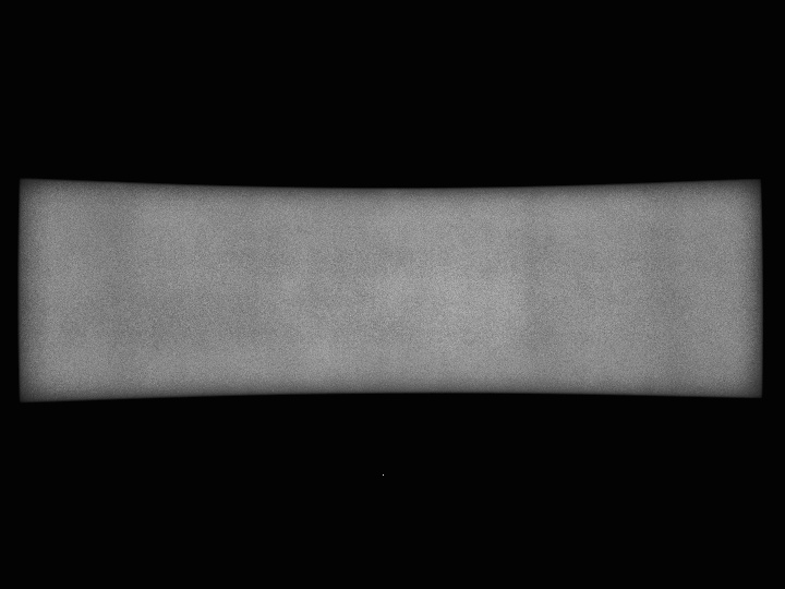
estimating brightness via dilation 10 iterations and np.maximum():
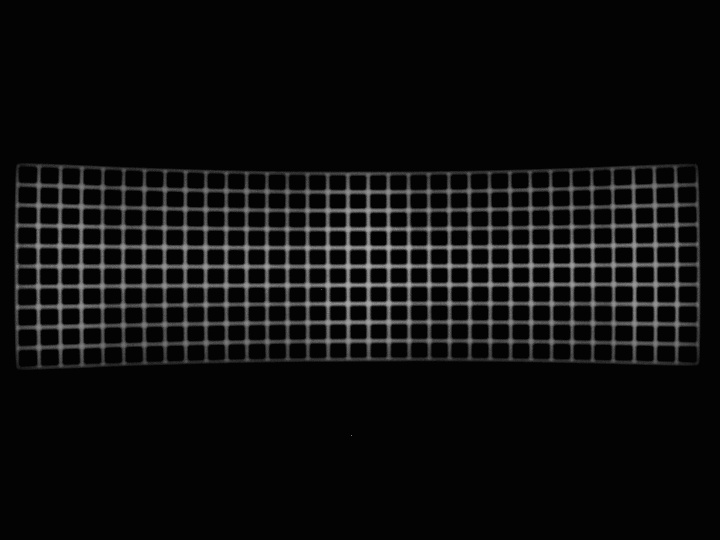
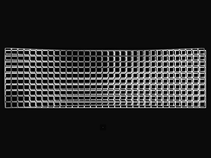
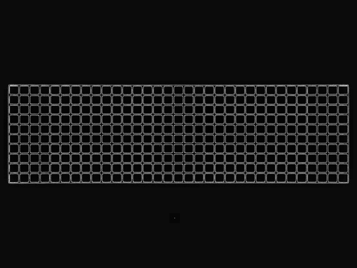
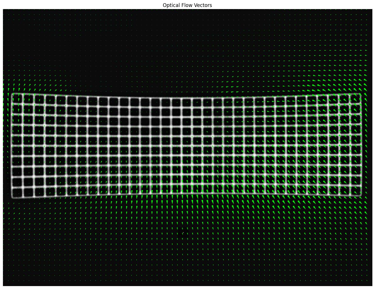
visualization of alignment:
first flow calculation: mean 3.571 px, 0.002 .. 9.147 px
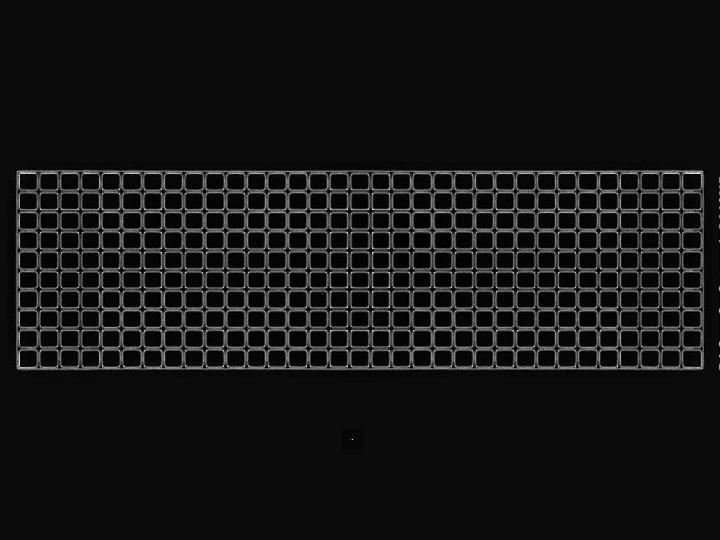
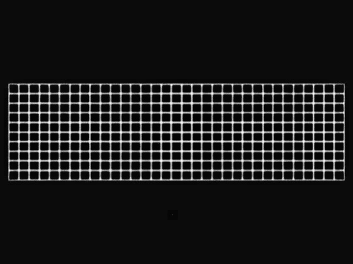
application of first flow yields this alignment:
second flow calculation: mean 0.116 px, 0.000 .. 0.433 px
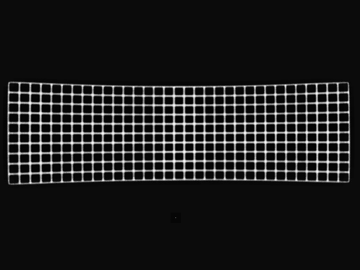
visualization of alignment:
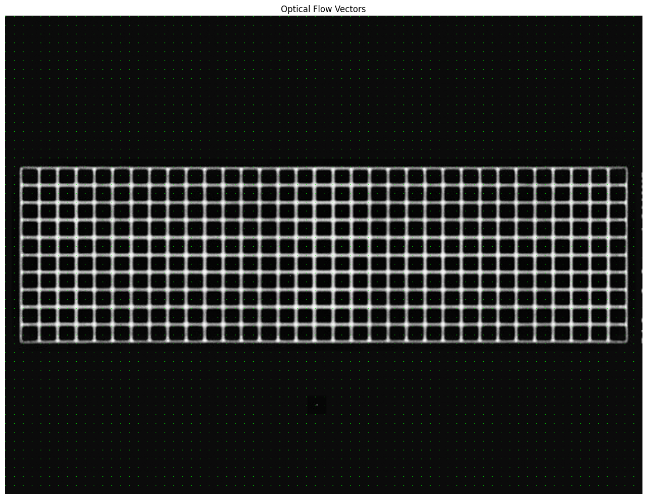
third flow calculation: mean 0.064 px, 0.000 .. 0.267 px
it’s basically jittering around from noise at this point, i.e. it has converged. the first flow calculation got it almost all of the way there. any iteration after that is just polishing.
cv.remap() uses fixed-point arithmetic, 5 fractional bits. that alone limits the precision (and accuracy) of the result. 2**-5 == 0.03125, so that’s one lower bound on the subpixel precision. the previous (incremental) flow field’s average being 2-3x that limit tells me we’re done iterating.
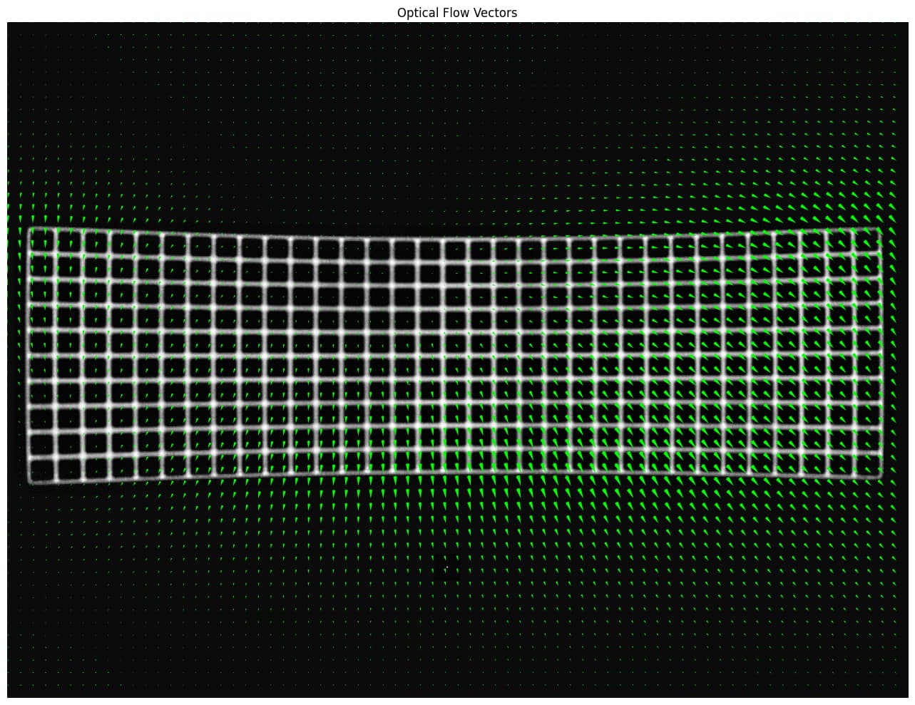
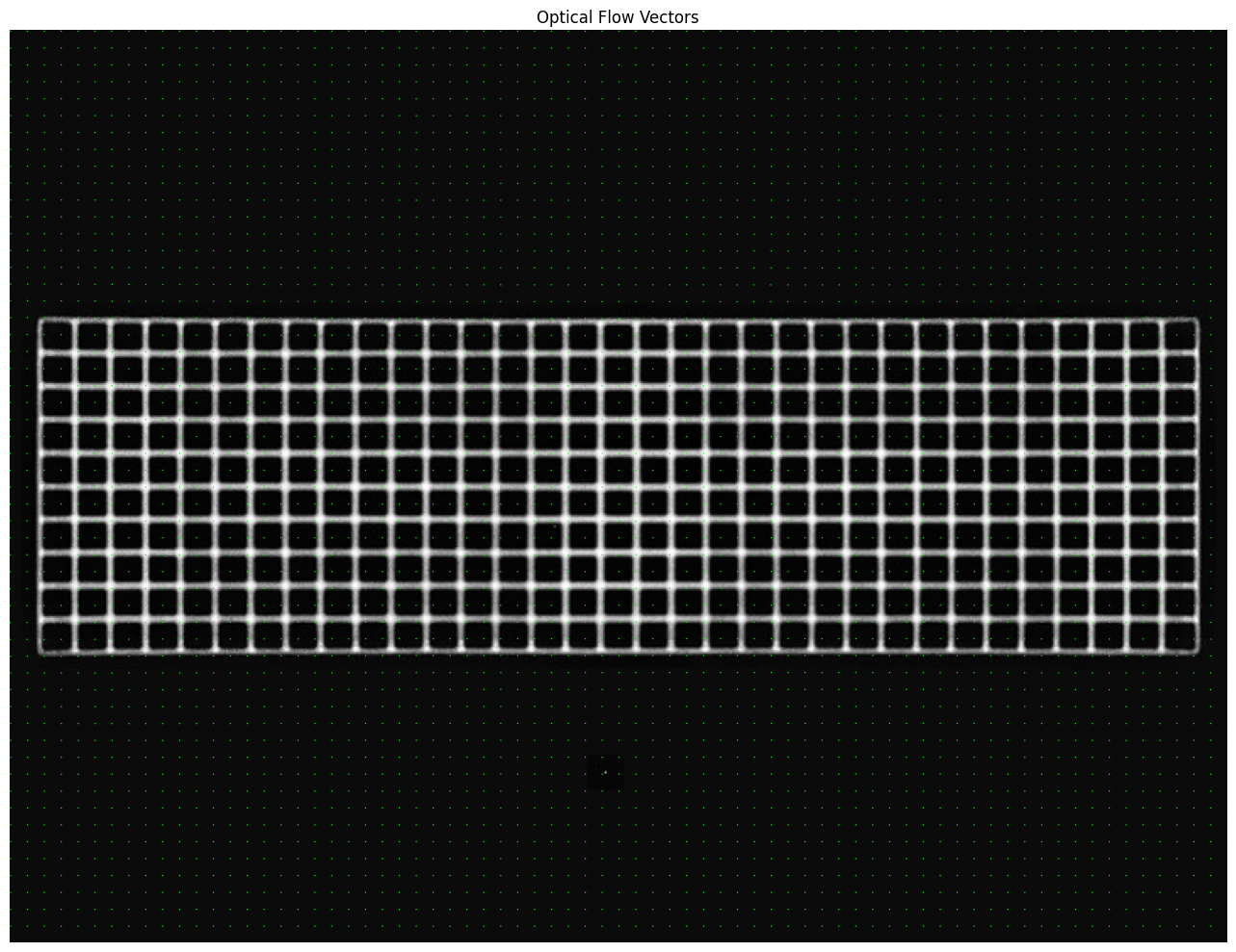
final flow/map: mean 4.002 px, 0.015 .. 10.089 px
NB: the sliver of “dots” in the top left is actually literally zero. the arrows to the south of it are actually non-zero but small. scale is 1.
and that’s the result:
those bright pixels at the right edge of the difference image come from the way I copy images out of the notebook from VSCode. they are not present in the notebook on github.
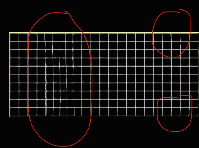
the flow/warp field might benefit from lowpassing, as I did a while ago in the other post. wherever the optical flow has no “support”, i.e. no texture/structure to refute any alleged flow, the flow can be whatever. be aware of that. it’s only sensible where the calibration had actual support.
I tried some of the parameters to DIS optical flow. block size had to be increased to at least half the grid spacing, or else it might misassign blocks (“slipping gears”, fencepost problem). optical flow is capable of calculating fine structures. here you’d want it generally smooth, because fine structure would give you strange folds and creases. I’m assuming that the patch size limits the level of detail implicitly, which is to your advantage.
if you need to tease more subpixel precision out of this, the interpolation modes to remap() could be explored. cubic noticeably improved on linear, in terms of the stats I pull out of the flow/warp fields.