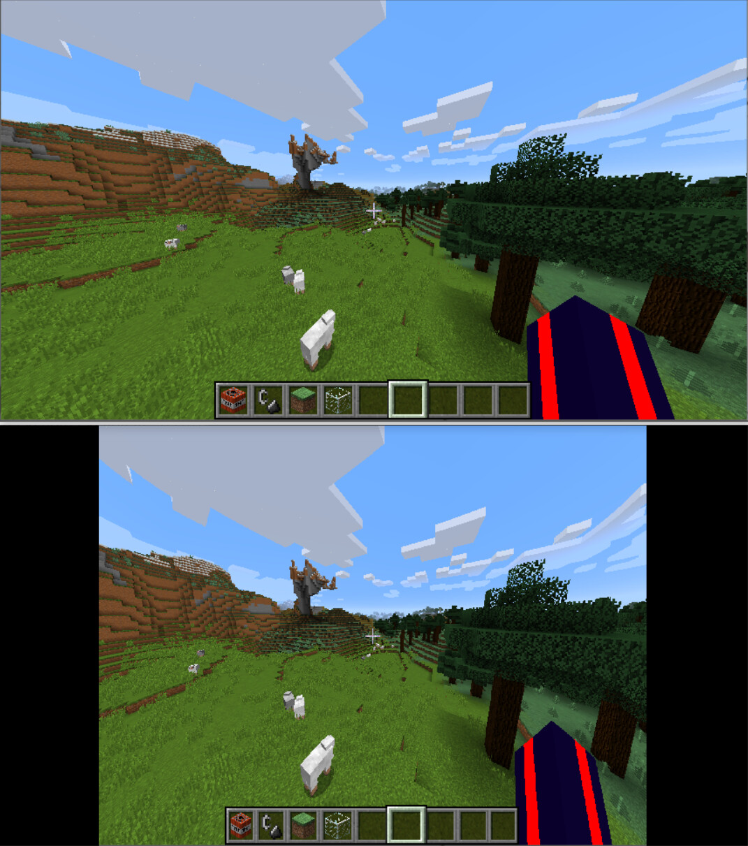
“an agent”
have no fear of being very very very overly specific. in academic circles, abstraction is sold as a virtue when it’s really a vice, a sin, a crime, especially inflicted upon academics. value examples over definitions, always. examples are cheaper to understand than a definition.
I haven’t seen signs of understanding for some points so I’ll review the whole thing and swing the mallet harder. my goal is that this all makes sense to you and your questions aren’t merely answered but disappear entirely because your model of the world has changed to make them superfluous.
in a computer you want to deal with flat things on a square grid.
everything that isn’t flat has to be mapped/projected to a flat thing. cylinders aren’t flat but they’re trivial to map (flat sheets bend). spheres aren’t flat, and they are not trivial to map.
a map is not reality. it’s allowed to have downsides. you can compensate for these downsides. you use a map because it has upsides, a common one being simplicity (a flat square grid of pixels is very simple to handle).
assuming you really really need a complete sphere mapped, you’ll have to do some calculations to turn distances and velocities on the map into angles and rates of rotation on the sphere.
I’d suggest an Equirectangular projection - Wikipedia, if you get there. coordinates on it directly map to angles on the sphere by nothing but a factor.
as long as you have a single normal camera, you can do this:
(2) you calculate the optical flow (in pixels of difference) on the picture.
(1) you calculate the correction map to that, based on the angle between the optical axis and the ray going through the pixel, because that angle says how something moving near that ray is projected near that pixel. these coefficients are static and they’re factors, so you can do this once, before you do anything else. this correction map, for any pixel position, converts pixel distances into angles or rates of rotation.
(3) you correct the optical flow using that map. division in the following example, or calculate inverses to get to use multiplication.
the exact math involves some trigonometry and some derivatives. I’ll show you difference quotients first because they’re easier to visualize… “eps” shall represent something moving a little bit (the optical flow).
at the center of the map (angle zero), you’d have a factor of 1 because
tan(eps) ~ eps
>>> a = 0 * pi; eps = 1e-8; (tan(a+eps) - tan(a-eps)) / (2*eps)
1.0
further away from the center you’d get larger factors because there the same angle difference moves farther:
>>> a = 1/4 * pi; eps = 1e-8; (tan(a+eps) - tan(a-eps)) / (2*eps)
2.0000000156006337
this difference quotient represents a derivative:
d/dx tan(x) = 1 / cos(x)^2
the calculation becomes:
>>> a = 1/4 * pi; 1 / cos(a)**2
1.9999999999999996
now you just need to know for every pixel what angle a ray through it has to the optical axis. you know the field of view (FoV) of your camera because you calibrated it.
equation from the camera matrix for horizontal FoV: a ray on the right edge of the view (hfov/2) is mapped to the right edge of the picture (usually, cx = width/2)
tan(hfov / 2) * fx + cx = width
| cx = width/2
tan(hfov / 2) * fx = width/2
equations get simpler if you first subtract the optical center (cx,cy) from pixel coordinates.
tan(x_angle / 2) * fx + cx = x
x_angle = arctan((x-cx) / fx) * 2
feel free to investigate whether you can separate these calculations into x and y direction on the picture, or whether you have to do anything more complicated. since camera sensors have a square grid, usually fx = fy is a fair assumption, so that makes things simpler.