Is there a way to increase the quality of feature matching by using (erosion, threshold, dilation/erosion etc..) prior to feature detection?

I am attempting to think through a strategy on matching and aligning images of coins

currently using typical process:

  1. convert images to grayscale:
  2. Detect features (AKAZE)
  3. Match descriptors (knnMatch)
  4. Filter matches
  5. findHomography(RANSAC)
  6. warpPerspective()

the problem:
When I match 2 images of a coin and the coin is greater than a 20% difference in quality (due to wear and erosion of the coin face) there are less matches and the script produces bad results. this is expected as the 2 pictures are quite different if there is a lot of erosion.

my question,
To gain a higher number of quality matches is there a strategy I could use at step 1 (erosion, threshold, dilation/erosion etcā€¦) that would produce better results?

example here: iCollect (coins are within a 20% difference in quality and it works OK) but go past this and it fails.

other ideas welcome as well.

thank you.

welcome.

best strategy is to change your lighting.

your two pictures there look quite usable. result looks good too. could you provide pictures that give you trouble?

by the way, assuming mint year is on the bottom of a coin and readable, you could attack this approximately with OCR. find the year (speculatively rotate until OCR spits out a good number) to turn arbitrary coins upright.

lighting Yes, been reading about that. This was a good paper: 07045977.pdf (gwu.edu)

here is an example that doesnā€™t work. this is a high grade version of the coin. the reflection seems to be the biggest issueā€“that is what led me to think about changing the image prior to making it gray:

However, when I attempted to compare the quality of matches of the images that worked as originals to other forms of the image to attempt a higher match quality nothing worked as good as the originals in gray

OCR
I was fooling with Tesseract a bit on the year digits and after a few hours of not being able to read the date reliably I gave up. Here is a great article on different aspects of the issue and some private databases to use with ML. The issue I see with using it for alignment is that when our users take photos of coins there is always the issue of angle so in order to do any good ML or contour analysis we have to have the image line up as best as possibleā€“hence, this current research. One simple feature that would come out of this is a brute force way to detect counterfeits ā€“ its not a great way to do it but often times counterfeits noses/ear/neck of the image etc. donā€™t line up with the original.

single views of reflective objects will always play tricks on you. I would speculate that the extracted features of differently lit coins differ in some significant way, and that makes matching difficult.

youā€™re right to call this research. there is research on dealing with reflective objects. you might have to impose restrictions on lighting (matte box and whatnot). maybe even require specific backgrounds (textured surface, linen cloth, graph paper). or even require multiple views and do a 3d reconstruction, even if only to condense it back down to a non-reflective view of the coin.

Iā€™d like to see feature matching and homography fail on a pair of coins that look like they should match. I havenā€™t seen the failure yet.

1 Like

Iā€™d like to see feature matching and homography fail on a pair of coins

at the site iCollect

simply press the ā€œcompareā€ button and use this image Morgan-40o.jpg (1000Ɨ1000) (icollect.money)

then press the ā€œAlignā€ button

I would speculate that the extracted features of differently lit coins differ in some significant way, and that makes matching difficult.
This is why I though it might be useful just to use a drawing of both images or black version but neither worked. I think that messes up the descriptors

Iā€™d recommend drawKeypoints with DRAW_RICH_KEYPOINTS. that draws size and angle as well. if you feel like it, get the inlier mask from the RANSAC step and visualize the consensus matches vs the ones that were input.

keeping 8 points in good_matches vector out of 6744 contained in this match vector

I tried it with a ratio of 0.8 and 0.75 and that only gave me a few more matchesā€¦ but findHomography gives an implausible result anyway, seems to be overwhelmed by inappropriate matches. perhaps play with the ratio to get more matches, and play findHomography parameters such as the reprojection threshold and maxiters arguments.

those pictures are very detailed. I suspect a lot of descriptors get wasted on very low level features like scratches. the matching process doesnā€™t take scale into account, and findHomography doesnā€™t take that into account either (unless akaze encodes that info in the descriptor vectors but I donā€™t think so).

try a pyrDown on both images before detectAndCompute. thatā€™ll remove those high frequency features. the resulting homography matrix can be adjusted to work on the full size pictures if you need (just needs multiplication by scaling matrices from both sides).

1 Like

@crackwitz Iā€™m working on the recommendation you made about showing the inliers. Iā€™m finding an issue that I donā€™t understand.

So i create the points1 and points2 arrays and associated mats. This works great. Here is an example of the first few points in each:
image

However, when I go to make deconstruct the inliers/outliers array that is produced by findHomography / RANSAC as follows:

let findHomographyMask = new cv.Mat();
let h = cv.findHomography(mat1, mat2, cv.RANSAC, 3, findHomographyMask);

I get an array that looks something like this:
image
which is great and lines up against the points2 array as Iā€™m reading that it should. However, here is the problem. look at the highlighted point: itā€™s a ā€œyā€ coordinate of a keypoint. and is flagged as an ā€˜outlierā€™ but itā€™s ā€œxā€ value was flagged as an ā€˜inlierā€™.

am I misunderstanding how this works?

thanks.

ps. there is bug report on DRAW_RICH_KEYPOINTS. I posted it as a followup to a closed bug. Iā€™ll work that after I get the inliers figured out. I think this is key to understanding the issues as you pointed out.

the inlier mask contains one boolean for every whole point.

1 Like

your comment: the inlier mask contains one boolean for every whole point

just to clarify what you are saying: I think you are saying because I have 2 booleans for every keypoint I am doing something wrong. is that correct? If that is the case it may have to do with me flattening the points arrays to fit them into the mats with 1 column to get them to function in the homography.

Iā€™ve traced a few keypoints from start to finish to show you what I mean:

OR are you saying, I should do boolean math and (x=1, y=0) [x=650.1663208007812 y=47.47700119018555] would be 1+0=1 and this would be an ā€˜inlierā€™?

Iā€™m reading the maskā€™s Mat like this:

for (let i = 0; i < findHomographyMask.rows; ++i) {
        console.log("inliers", findHomographyMask.data[i], "points2: ", points2[i]);
}

sorry to ask for clarification, I just donā€™t want to screw this part up because the next set of decisions will using this.

that

when you give findHomography two mats that each contain, say, one column and 234 rows of 2-channel data, it will give you a boolean mat that is one column and 234 rowsā€¦ and single channel of course, because each boolean goes for a whole point, not individual coordinate values.

when you flatten one of those 2-channel mats into 234*2 = 468 valuesā€¦ you need to account for that.

1 Like

so I think there is a bit of a catch 22 here.

There doesnā€™t seem to be a way to get findHomography to work with opencv.js using anything but 1 column mats. footnote: Iā€™m not sure itā€™s even possible to put data into a 2 column mat in javascript (see here). If you use 1 column mats then the RANSAC mask gives back 1 column binary data which like you pointed out is useless.

or am I missing something that I could do with the returned 1 column RANSAC mask data?
or am I correct, that without providing findHomography a 2 column mat with x and y Iā€™m hosed?

yes, use that and line it up against your point data. account for shapes and flattening. I disagree with the rest of the post. the data is certainly not useless. I see that getting data into the right shape seems to be tricky in the javascript API, but it appears to be doable.

1 Like

OK, here is how I backtracked to the good ā€˜inlierā€™ keypoints. probably not the most efficient way but brute force as a test.

you can see the output on iCollect and compare the image with all the matches with the one with the good matches.

let me know what you think before I start working on the rest of your feedback.

let findHomographyMask = new cv.Mat();//test
let h = cv.findHomography(mat1, mat2, cv.RANSAC, 3, findHomographyMask);
if (h.empty())
{
	alert("homography matrix empty!");
	return;
}
else{
	let good_inlier_matches = new cv.DMatchVector();
	for (let i = 0; i < findHomographyMask.rows; i=i+2) {
		if(findHomographyMask.data[i] === 1 || findHomographyMask.data[i+1] === 1) {
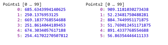
			let x = points2[i];
			let y = points2[i + 1];
			for (let j = 0; j < keypoints2.size(); ++j) {
				if (x === keypoints2.get(j).pt.x && y === keypoints2.get(j).pt.y) {
					for (let k = 0; k < good_matches.size(); ++k) {
						if (j === good_matches.get(k).trainIdx) {
							good_inlier_matches.push_back(good_matches.get(k));
						}
					}
				}
			}
		}
	}
	var inlierMatches = new cv.Mat();
	cv.drawMatches(im1, keypoints1, im2, keypoints2, good_inlier_matches, inlierMatches, color);
	cv.imshow('inlierMatches', inlierMatches);
	console.log("Good Matches: ", good_matches.size(), " inlier Matches: ", good_inlier_matches.size());

Here is an easy way to visualize and compare to the graphic in a previous post above:

also, not sure yet why when I pyrDown the matrix gets hosed (you can see it as I put an option for pyrDown at the top). Looking into that now but all iā€™m doing is calling it at the beginning of the script. makes me think this logic in the homography is still not correct.

correction, knn % of .5 works with pyrDown but now Iā€™m wondering how to determine automatically what factor to useā€¦

cv.pyrDown(im1, im1, new cv.Size(0, 0), cv.BORDER_DEFAULT);
cv.pyrDown(im2, im2, new cv.Size(0, 0), cv.BORDER_DEFAULT);