Hello CHR,
If you have implemented the scaling, you will see that it has no effect on the conversion to rotation matrix.
From the UR, you need to make sure you are scaling the translation w.r.t what units you want, actually the most important is that it corresponds with the units you have chosen for the camera poses.
UR uses axis angle rotation, therefor using rodrigues rotation formula will result in the corresponding rotation matrix.
My pipeline:
Collect pose from robot [X,Y,Z,RX,RY,RZ].
Separate the vector into a rotation vector and translation matrix 3x1.
Using rodrigues on the rotation vector (scaled or not, makes no difference).
Push back the rotation matrix into a vector of matrices (std::vector< cv::mat >).
Push back the translation matrix 3x1 to a vector of matrices.
Thank you very much for your reply. I have tried following your pipeline and looking at your code snippets. Unfortunately I am unable to obtain useful results. Based on manual measurements I expect a translation of [0, 70, -140] (mm), but instead I get the following:
I have ensured that the images are loaded in the correct order. I just don’t know if it is my code being wrong or if it is the robot pose I’m reading wrong from the UR5.
I have uploaded my material here: Source Material
Any help would be highly appreciated!
I just tried your data with my code, and i recieve the same results as you.
Your code is correct, but maybe your data is not solid enough.
What are your approach towards collecting your data?
Some tips towards a hand eye calibration can be found in, besides the information from their page, you want to have unique robot poses over the working area, your application needs to run.
Are you completly sure that your images matches the same time stamp of the robot pose, and they are in the exact same order? I suppose you created a function were you record both simultaneously.
Thank you so much for checking with your code.
You were correct - it was the robot poses being wrong. Now I achieve correct results!
Thanks for your commitment!
Hi Guys, I am doing the same hand calibration with the UR. I am just not sure about the information of the actual TCP pose from the UR side. How do you guys solve it? I meant I have tried to generate the rotation matrix from the RX,RY and RZ with the Rodrigues. It does not give me proper result. The polyscope was not giving me a good result.
On the other side, after getting the transformation matrix from TCP Position based in Base Frame. We should invert / transpose the matrix and multiply the translation vector with the -1*inverted/transposed rotation matrix. I do not see this transformation in the script from @Anders and @dahonora . Or have you guys already obtained the base pose based on the TCP frame?
I am using the getActualTCPPose()-Function from RTDE.
After that, I extract the rotation and translation vectors. Translation vector would be scaled with 1000 to get mm in unit. And the rotation vector is scaled and I used Rodrigues operator from OpenCV to obtain the rotation matrix. Since I wrote the code with python. I have checked the value of this matrix with scipy and it delivers the same output of rotation matrix too. The TCP is set at the end flange (X,Y,Z,RX,RY,RZ: 0,0,0,0,0,0). My camera is mounted via a synchro-flange like this picture:
I have read the description in OpenCV. At first, it was not so easy to understand the notation of the homogeneous transformation. Since I had different notations from the lecture at the university.
From my understanding, we should do following steps:
Extract robot TCP → get R- and T- Vector for the TCP.
Take image of checkerboard → findCheckerBoard + solvePNP → get R- and T-Vector for the target w.r.t camera.
Feed all of the input to the calculateHandEye-Function from OpenCV.
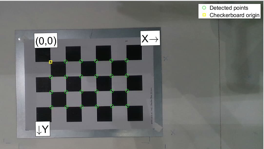
I have found the essential problem here. The problem is by using the checkerboard as the calibration target. Please have a look at the picture below and in the next replies ( I have a limited number of embedded uploads in this forum ).
(figure 1. Pose A)
The checkerboard does not have a proper reference to what is your upside and downside. In some poses, there is ambiguity. Imagine like when you take a planar orthogonal image from the target in figure 1. And then you rotate your TCP 180° into figure 2. You see like the system failed to recognize the starting point and the orientation of the target board.
After changing the checkerboard into a charuco board yesterday. I have got proper results, where all results from the different methods delivered converged values in rotation and translation. It does not mean that checkerboard calibration would not work. But if checkerboard would like to be used here. We need to use a simple and deterministic image pose. On the other hand, charuco board offers a fool-proof solution for newbies like me
Tomorrow I will prove the transformation matrix from my system and would inform you about its accuracy of it!
Yes, I have tried to model the frames. The fastest method is by using Matlab tool. With the checkerboard images from before, I did not recognize any suspected result.
I can see you use calib.io. Fun fact, it was my old professor. If you have read some of the articles/posts on his page, you would learn some good practices when calibrating. → Information
It is very nice you spotted the problem yourself. When you design the checkerboard target such a 180-degree rotation ambiguity can occur if either both sides are even or odd.
To solve you problem you need to design either another patteren. In order to be rotation-invariant, the number of rows needs to be even and the number of columns odd, or the other way around.
However, I would just keep the charuco targets, they are more robust. And one big advantage is that you can collect images from the far edges, as they are uniquely coded and identifiable. Compared to the chessboard where the entire chessboard has to be visable, charuco overcome this limitation.
Anyways, you can try with the chessboard, then you also have something to compare with. I reached a convergence of around 14 images and robot poses.
When you have calculated the hand-eye transformation, you can plot it all together (maybe with less data points) and have a nice visable view of the camera pose and robot pose w.r.t the calibration target.
I hope this helps you!
You are more than welcome to write again. I would recomend to read the information I’ve linked.
Thanks for the elaborate discussion, it really helps!
However, there is still some accuracy error in my case, in which the position along the z-axis reaches about 10mm error while the x- and y-axis seem to be slightly better (less than 3mm). As the rotation errors look fine, which are less than 1 degree for all rotation axes, here I just printed out the translation of the checkerboard to the robot base (they are supposed to be as close as possible as the board didn’t move).
Could I get any suggestions from you? I have tried to catch the images with poses as different as possible, but this is the closest result I can get so far…Any help would be great!
In case my script for calculating the transform between the gripper and the camera has some bug, I have also uploaded my dataset here: eye_in_hand_calib_data - Google Drive
. Could anyone run through my data with his/her code to see if we could get the same result or not?
You could get the transforms from the json file with this piece of code:
filename = "data/data_extrinsic.json"
axes = 'sxyz'
with open(filename, "r") as json_file:
    loaded_data = json.load(json_file)

# Now, 'loaded_data' contains the data from the JSON file as a Python dictionary
rmat_all_grip_to_base_json = np.asarray(loaded_data['rmat_all_grip_to_base'])
tvec_all_grip_to_base_json = np.asarray(loaded_data['tvec_all_grip_to_base'])
T_all_grip_to_base_json = np.asarray(loaded_data['T_all_grip_to_base'])
#######################
# rmat_all_grip_to_work = np.asarray(loaded_data['rmat_all_grip_to_work'])
# tvec_all_grip_to_work = np.asarray(loaded_data['tvec_all_grip_to_work'])
# T_all_grip_to_work = np.asarray(loaded_data['T_all_grip_to_work'])

rmat_all_chess_to_cam_json = np.asarray(loaded_data['rmat_all_chess_to_cam'])
tvec_all_chess_to_cam_json = np.asarray(loaded_data['tvec_all_chess_to_cam'])
T_all_chess_to_cam_json = np.asarray(loaded_data['T_all_chess_to_cam'])


R,T=cv.calibrateHandEye(rmat_all_grip_to_base_json,tvec_all_grip_to_base_json,rmat_all_chess_to_cam_json,tvec_all_chess_to_cam_json)
print(R)
print(T)